Well, this my self study blog. I dont need actually justify any change. I feel free to add/delete and change anything at any time I want. I think routingtelecom is too big. And it cames from a time when I was intending to start a company as Asterisk consultant. Then Telecom has something professional. As this idea pass away and it turned into a self study blog only, I think RoutiOS may be better. I love route as it is the truly and real process that allows any kkind of communication. And iOS is the most common and used term in this days. Cisco and Apple the sexiest world companies uses those three letters to designate the operating systems.
This is smaller and even more representativa but at the end is just a title. What I realy want is share more and more interesting stuff on it.
Thats the reason, thats my goal.
Sunday, April 26, 2015
Saturday, April 25, 2015
QUIC Protocol - The protocol Quick
The Internet traffic has grown tremendously in last years. The demand for faster Internet keeps growing and surprisingly we are working with protocols developed 40 years ago. Even http version largely used today (http 1.1) was developed around 90's.
It is not difficult to realize that we need to build faster protocols. Protocols able to handle the today's Internet.
TCP has made remarkable work until now and will do for many years ahead but TCP was developed in a totaly different scenario.
Companies has made huge effort trying to make things better. To delivery much better experience for users. And in this scenario, Google came with a brend new protocol called QUIC (Quick UDP Internet Connection).
Before deep dive in QUIC, it is important discus about another protocol also developed by Google, this one called SPDY. As mentioned before, http 1.1 is no longer indicated for today's Internet. It was developed in a time where web pages were static, load from one only source and one domain. Today´s web page are load from about 80 differents sources and about 30 domain. The web page is a big mosaic and each piece coming from one point of the world. Sure enough, to handle all of it is necessary a very smart and high performance protocol.
In this scenario Google has developed SPDY. The main goal of SPDY and QUIC is reduce Latency. It is all about latency. SPDY is a application protocol that works compressing,multiplexing and prioritizing data.
According to Google's SPDY definition, "SPDY is a multiplexed stream protocol currently implemented over TCP. Among other things, it can reduce latency by sending all requests as soon as possible (not waiting for previous GETs to complete)"
But, there's a problem here. As mentioned SPDY run over TCP and TCP has some characteristic that is not in accordance with the goal of SPDY low latency.
TCP has a known behavior called Head-of-Line Blocking. Since TCP only provides only a single serialized stream interface, if one packet is lost it will interfere in the entire SPDY communication. SPDY multiplex many stream over TCP connection but Head-of-Line Blocking cancels it.
A good example of this scenario can be seeing bellow:

If the red packet is lost, all other flows must wait.
To overcome this and others issues, QUIC comes to the scene. With QUIC, the above scenario has changed completely:

From now one, the improvement allowed by SPDY shows up. If the red packet is lost, the whole flow does not suffer anymore.
QUIC run over UDP for good reason. UDP does not perform three way hand shake as TCP. Its nature makes it fast. As QUIC aims to zero RTT it is impossible to run over TCP.
The following figure shows that concept:

With QUIC, Google aims the following goals. Those goals were taken from "QUIC: Design Document and Specification Rationale".
1-Widespread deployability in today’s Internet.
This is not easy to achieve. As we may know, Google can't perform any change in the Internet structure. SPDY and QUIC must be transparent on the Internet. Otherwise it will be blocked along the firewalls and router out there.
Perform change in TCP/UDP/IP headers only can be made by regulatory entities and it takes lots of years. Furthermore, the adoption of this changes can take even more time. Those protocol lives inside all kernel around the world and it is really complicate to get all those kernel upgraded.
2. Reduced head-of-line blocking due to packet loss
As we saw above, this is possible with QUIC.
3. Low latency (minimal round-trip costs, both during setup/resumption, and in
response to packet loss)
This is the main objective of the protocol
4. Improved support for mobile, in terms of latency and efficiency
5. Congestion avoidance support comparable to, and friendly to, TCP
6. Privacy assurances comparable to TLS
7. Reliable and safe resource requirements scaling
8. Reduced bandwidth consumption and increased channel status responsiveness
9. Reduced packet-count
10. Support reliable transport for multiplexed streams
11. Efficient demux-mux properties for proxies
12. Reuse, or evolve, existing protocols at any point where it is plausible to do so,
without sacrificing our stated goals
By achieving those goals, Google will have built a much more fast Internet. I doubt anyone has courage to say Google will fail in building such huge accomplishment. Considering the past and present of this remarkable company, we must wait nothing but the whole Internet structure transformed forever. As network engineer, we need to understand those protocols and any other to come to stay ahead of our time. Google has already proved its capacity in transform the way we live.
This is a "Quick" overview about this very interesting protocol. I'd like to go deeper and maybe perform some practical demonstration. But we can continue in another article.
What do you think about it ? Will Google really going to change the whole Internet by developing protocols like QUIC and SPDY ?
Is it possible a future where we will have Google Apps, Google operational System, Google Internet protocol and Google world wide network ?
It is really scary , isn't it ?
It is not difficult to realize that we need to build faster protocols. Protocols able to handle the today's Internet.
TCP has made remarkable work until now and will do for many years ahead but TCP was developed in a totaly different scenario.
Companies has made huge effort trying to make things better. To delivery much better experience for users. And in this scenario, Google came with a brend new protocol called QUIC (Quick UDP Internet Connection).
Before deep dive in QUIC, it is important discus about another protocol also developed by Google, this one called SPDY. As mentioned before, http 1.1 is no longer indicated for today's Internet. It was developed in a time where web pages were static, load from one only source and one domain. Today´s web page are load from about 80 differents sources and about 30 domain. The web page is a big mosaic and each piece coming from one point of the world. Sure enough, to handle all of it is necessary a very smart and high performance protocol.
In this scenario Google has developed SPDY. The main goal of SPDY and QUIC is reduce Latency. It is all about latency. SPDY is a application protocol that works compressing,multiplexing and prioritizing data.
According to Google's SPDY definition, "SPDY is a multiplexed stream protocol currently implemented over TCP. Among other things, it can reduce latency by sending all requests as soon as possible (not waiting for previous GETs to complete)"
But, there's a problem here. As mentioned SPDY run over TCP and TCP has some characteristic that is not in accordance with the goal of SPDY low latency.
TCP has a known behavior called Head-of-Line Blocking. Since TCP only provides only a single serialized stream interface, if one packet is lost it will interfere in the entire SPDY communication. SPDY multiplex many stream over TCP connection but Head-of-Line Blocking cancels it.
A good example of this scenario can be seeing bellow:
If the red packet is lost, all other flows must wait.
To overcome this and others issues, QUIC comes to the scene. With QUIC, the above scenario has changed completely:
From now one, the improvement allowed by SPDY shows up. If the red packet is lost, the whole flow does not suffer anymore.
QUIC run over UDP for good reason. UDP does not perform three way hand shake as TCP. Its nature makes it fast. As QUIC aims to zero RTT it is impossible to run over TCP.
The following figure shows that concept:
With QUIC, Google aims the following goals. Those goals were taken from "QUIC: Design Document and Specification Rationale".
1-Widespread deployability in today’s Internet.
This is not easy to achieve. As we may know, Google can't perform any change in the Internet structure. SPDY and QUIC must be transparent on the Internet. Otherwise it will be blocked along the firewalls and router out there.
Perform change in TCP/UDP/IP headers only can be made by regulatory entities and it takes lots of years. Furthermore, the adoption of this changes can take even more time. Those protocol lives inside all kernel around the world and it is really complicate to get all those kernel upgraded.
2. Reduced head-of-line blocking due to packet loss
As we saw above, this is possible with QUIC.
3. Low latency (minimal round-trip costs, both during setup/resumption, and in
response to packet loss)
This is the main objective of the protocol
4. Improved support for mobile, in terms of latency and efficiency
5. Congestion avoidance support comparable to, and friendly to, TCP
6. Privacy assurances comparable to TLS
7. Reliable and safe resource requirements scaling
8. Reduced bandwidth consumption and increased channel status responsiveness
9. Reduced packet-count
10. Support reliable transport for multiplexed streams
11. Efficient demux-mux properties for proxies
12. Reuse, or evolve, existing protocols at any point where it is plausible to do so,
without sacrificing our stated goals
By achieving those goals, Google will have built a much more fast Internet. I doubt anyone has courage to say Google will fail in building such huge accomplishment. Considering the past and present of this remarkable company, we must wait nothing but the whole Internet structure transformed forever. As network engineer, we need to understand those protocols and any other to come to stay ahead of our time. Google has already proved its capacity in transform the way we live.
This is a "Quick" overview about this very interesting protocol. I'd like to go deeper and maybe perform some practical demonstration. But we can continue in another article.
What do you think about it ? Will Google really going to change the whole Internet by developing protocols like QUIC and SPDY ?
Is it possible a future where we will have Google Apps, Google operational System, Google Internet protocol and Google world wide network ?
It is really scary , isn't it ?
Thursday, April 23, 2015
TACACS on Cisco Prime
This not intend to be an article like many others written in this blog. This aim to be a Tek-Tip more than a article, but, this is the kind of information I consider to be pretty valuable.
I like to write article to teach others the whole concept or even a How-To for some specific tool. But, I really like to share information I couldn't find on the Internet.
I was deploying a Cisco Prime migration from 1.3 to 2.2, maybe many of you don't know but it is not possible to perform that migration directly. It is necessary to migrate to a intermediate version first. Actually, Cisco PI 2.2 will be always a fresh start. What you can do for maintain you old environment is backup/restore your old database. The versions Cisco allows you perform backup to be later restore on Cisco PI 2.2 is:
Cisco Prime Infrastructure 2.1.2 (with the UBF patch)
Cisco Prime Infrastructure 2.1.1 (with the UBF patch)
Cisco Prime Infrastructure 2.1.0.0.87
Cisco Prime Infrastructure 1.4.2
Cisco Prime Infrastructure 1.4.1
Cisco Prime Infrastructure 1.4.0.4
In my case, I was in 1.3 version. Then I decide backup the database and restore in a 1.4.0.4 first. The first problem found here was about platform mismatch. I was not completely aware about the old server and choose a PI 1.4 considering the size of the network. Then I choose a small one. Therefore, as the old server was deployed as a Standard version, I should deploy a Large one. The first situation I faced was about partition sizing. This take me to write a article showing how can we change partition size on Cisco Prime and worked as expected. You can see it here Cisco Prime Partition Resizing
Well, still not aware of this platform details, I did partition resizing and move to the next step: Perform database restore into PI 1.4.
At this time I figured out a mistake. Among 9 steps required for a complete restore, at step 3 I received the errors message: CPU count mismatch.
Then I figured out that I was working with different platforms. Only after redeploy the PI 1.4 as Large, I could finish the restore.
Here you can find a reference:

One last problem was about to be discovered. After I restored the database I lost access to the Web Cisco´s Prime Web Interface.
I had full access through command line but I couldn't via web. To try mitigate this issue, I performed a TCPDUMP at linux level and tried to access the Web interface. I see the server trying to sending authentication request to a TACACS server.
This make sense, after all I restored a database from a server that was using TACACS. And this was an evidence that things were doing well. But, how could I overcome that issue ? It is not possible at that level, allows the server to communication with TACACS. furthermore, that server 1.4 was not supposed to exist on the network for long time.
As I had access through CLI, I performed a database backup to a FTP server and restored into PI 2.2. The result was the same. CLI access but no Web interface access.
Then I start to look for how can I solve that problem. How could I disable TACACS via CLI.I performed many searches on Google and Cisco docs but by no means I could find a clue. No answer.
Only after open a Cisco TAC I could get the answer. This is quite simple but I couldn't find that written in any doc out there.
The solution is change the root password. That's right.
# ncs
password root password <new-password>
Cisco Prime try to reach TACACS server first and than the local authentication. As we can see below:

As we can see, once checked TACACS+, the option "Enable fallback to Local" is checked as well and you can determine between two option. The default is "ONLY on no server response" or you can choose "no authentication failure or no server response".
Back to my scenario, as TACACS server doesn't respond, it was trying local authentication. But, it was a restored database then it is necessary reset root password. It worked for me in 1.4 and 2.2.
Just to complete the Tek-Tip, the backup/restore was a success. All the information was restored and I have a brand new environment with all the old information.Back to my scenario, as TACACS server doesn't respond, it was trying local authentication. But, it was a restored database then it is necessary reset root password. It worked for me in 1.4 and 2.2.
I hope this can help someone else because this is a quite common scenario.
Monday, April 13, 2015
QoS deployment Challenge
QoS, as any other kind of dimensioning, is really challenge. A perfect QoS deployment depends on a really good understanding of the traffic flow and this is something really hard to achieve. Most, if not, all companies out there, have no idea of what is going on through your cables and fibers or wireless.
But, considering that a company out there wants to apply QoS within your network, it is necessary perform some maths and try to get reasonable values based on the traffic and application in use.
Theoretically, traffic is divided in four categories:
-Internetworking Traffic - Basically routing protocols and others protocols used to run the network
-Critical Traffic - Voice,Video,etc
-Standard Data Traffic - Data Traffic like HTTP
-Scavenger Traffic - Traffic not important and sometimes not desirable.
Technically, things happen very deeply in the packets and frames. Understanding QoS involves a deep understanding of bits functioning on a packet. Therefore, so important as know the function is handle it. Is to be able to change those bits according to Customer requirements in order to shape the traffic.
The traffic needs to be Classified first and classify means mark packets first, make them different from each other, put color on it. The way to do that is changing specific bits within a packet or using Access-List and differentiate the hole packet within a packet flow.
To start a fresh QoS deployment is considered to be a good practice deploy some device on the network able to identify all kind of traffic and generate reports based on traffic types and percentage. At this point, you need not perform any kind traffic control, only identify which kind of traffic goes back and forth on the network and which percentage they occupy in the whole traffic.
I've never performed a QoS project so far, but, just like site survey, the proceed above described is not common as it should.
Anyway, from now on we are going to focus on QoS theory. As said above, traffic needs to be classified in any point of the network. The marking can be done at layer 2 or layer 3 of OSI model. Layer 2 frames has a field called CoS (Class of Service) available in the 802.1p

802.1p is part of 802.1Q. It is expected to be seeing only in trunks links. Access Ports has no way to perform this kind of Marking.
Packets can be marked at Layer 3 OSI model using the ToS field.

As we can see from the figure, ToS field is within the IP Packet and is divided in 8 sub field. The function and interpretation of this sub field will be discussed in detail on the next section.
CoS field has 3 bits and 8 possible values whilst ToS has 8 bits and 64 possible values.
The interpretation of the bits has two definition: IP precedence and DSCP (Differentiate Service Code Point). Well, we are going too deep here.
The fact is,this is all about interpretation. IP Precedence uses only the first three bits whilst DSCP use 6 bits. Two bits are used for congestion.
All this is pretty evident when you look at the table bellow:
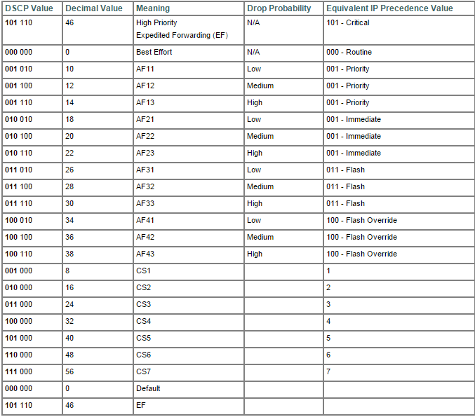
Basically, this tables summarizes all we need to know about QoS in terms of bits.
We can see on the right that IP Precedence has less classes in which we can mold our traffic. In the other hand, on the left we can see that DSCP is plenty of possibilities. We can spread the traffic out to all this classes.
Despite all this value, DSCP can be divided in basically four classes: Best Effort,Assured Forwarding,Expedited Forwarding and Class Selector. Best Effort means no QoS, Expedited Forwarding means the higher priority a packet can have, Assured Forwarding offers many possibility and Class Selector has a spacial meaning.
In terms of bits Best Effort is represented by 000, Assurance Forwarding is represented by 001 to 100 and Expedited Forwarding is represented by 101. Class Selector represent the situation in which last bits is set to zero thus mapping IP precedence and CoS perfectly. For example, the sequence 011000 could be written as AF 30 or CS3. We can see on the table from the CS1 to CS7. In all this case there were a perfect match between CoS and IP Precedence.
We can see in the table above,on the second column, called Decimal Value. DSCP is actually by a decimal value, this make things easier to white and read.
For a Wireless Engineer, it is not expected to know all this bit's functions. But, I personally don't like to narrow down my knowledge. Then, I want to know everything!
Considering that now you know all the bit's functions, it is time to organize all the information and get familiar with Queues and device configuration.
There are basically three kind of Queues:
-Priority Queue (PQ)
-Custom Queue (CQ)
-Weighted Fair Queue (WFQ)
PQ- One Queue being prioritized among all others Queues. Don't matter what.
CQ - Load balance the traffic among many Queues
WFQ- In its basic form, it allows for prioritization of smaller packets and packets which the ToS field is higher.
R1(config)# policy-map MyPolicy
R1(config-pmap)# class MyClass1
R1(config-pmap-c)# bandwidth percent 20
R1(config-pmap)# class MyClass2
R1(config-pmap-c)# bandwidth percent 30
R1(config-pmap)# class class-default
R1(config-pmap-c)# bandwidth percent 35
R1(config-pmap)# end
First of all, we define a policy-map. After all, it is not enough only create Queue. It is necessary apply those Queues somewhere and the way we do that is through Policy.
Inside the Policy Map we create Classes. Here we named it MyClass1,2,etc. At the end we have a default class. It is somewhat like firewall rules. If something does not fit in any condition then it will fall in default class.
There are yet some variances of those Queues:
-CBWFQ(Class-Based Weighted Fair Queue). It allows you to distribute traffic inside classes.
-LLQ (Low Latency Queue) This a variance of the Queue explained earlier. In this scenario, one Queue works like a Priority Queue,therefore, the amount of traffic allowed is limited. The other Queue is served just like normal CBWFQ.
Lets see, in terms of commands, how things goes:
R1(config)# policy-map MyPolicy
R1(config-pmap)# class MyVoiceClass
R1(config-pmap-c)# priority percent 20
R1(config-pmap)# class MyClass2
R1(config-pmap-c)# bandwidth percent 30
R1(config-pmap)# class class-default
R1(config-pmap-c)# bandwidth percent 35
R1(config-pmap)# end
R1#
When it comes to LLQ, we can see a new command: priority and then the percentage. In this case, it was defined 20 %. It means, this Queue, generally used for Voice, can use up to 20% of the whole bandwidth, but, not more then that. If the traffic arrives to 20%, packets starts to be dropped.
Besides this Queues, we can find Congestion mechanisms. WRED (Weighted Random Early Detection). It is very interesting because it uses a natural mechanism of TCP to control traffic congestion. By dropping some packets and forcing retransmission, TCP handshake reduce the Window ,the amount of traffic is consequently reduced.
To enable this future, just type random-detect at interface configuration level.
Well, it works like a charm for TCP but what about UDP ?. UDP does not use Window. Well, I intend to wright down another article about QoS on Wireless network, just like I did with Multicast. That, we will see about CAC and the mystery of UDP congestion control will be solved or handled at least.
We also have one more type of congestion control called LFI (Link fragmentation and Interleaving) Basically it breaks bigger packets in smaller ones avoiding delay with large packets.
That´s all for now. It is important to say that QoS is an end-to-end deployment. It is an waste of time if you deploy QoS considering all the requirements but in one point,only one single point you do not. Everything you done has gone.
I hope you guys enjoy the article. I am working in Wireless QoS article, after all, this supposed to be a Wireless career path. This supposed to be a self study blog and current I am trying to get my CCNP Wireless.
Flavio Miranda.
Wednesday, April 8, 2015
Cisco Prime Partition Resizing
It is expected that when you run an image .iso or .ova, whatever, everything is gonna be all right at the end of the process. After all, we are handling a blackbox created by someone really specialized. But, you may find some surprise out there.
I was happily performing a restore from Prime version 1.3 to a 1.4. Nothing could be wrong on that, I thought! But not!
When I was running the restore command, I got the following errors:
Stage 1 of 9: Transferring backup file ...
-- complete.
Stage 2 of 9: Decrypting backup file ...
-- complete.
Stage 3 of 9: Unpacking backup file ...
--complete.
ERROR: Not enough space to continue restore
What ? How is that possible? My Virtual Machine has 1 Tera on its HD!!
Well, looking for some information on the Internet, I have found some interesting tips. According to that, Cisco Prime wrongly allocate the /opt partition sometimes. In my case, it has reserved 120 G and was using 60%. That´s the problem.
ade # df -h
Filesystem Size Used Avail Use% Mounted on
/dev/mapper/smosvg-rootvol
3.8G 295M 3.4G 9% /
/dev/mapper/smosvg-storeddatavol
9.5G 151M 8.9G 2% /storeddata
/dev/mapper/smosvg-localdiskvol
29G 235M 27G 1% /localdisk
/dev/sda2 97M 5.6M 87M 7% /storedconfig
/dev/mapper/smosvg-home
93M 5.6M 83M 7% /home
/dev/mapper/smosvg-optvol
120G 68G 46G 60% /opt
/dev/mapper/smosvg-varvol
3.8G 115M 3.5G 4% /var
/dev/mapper/smosvg-usrvol
6.6G 1.2G 5.1G 19% /usr
/dev/mapper/smosvg-tmpvol
1.9G 36M 1.8G 2% /tmp
/dev/mapper/smosvg-recvol
93M 5.6M 83M 7% /recovery
/dev/mapper/smosvg-altrootvol
93M 5.6M 83M 7% /altroot
/dev/sda1 485M 18M 442M 4% /boot
tmpfs 12G 6.0G 5.8G 52% /dev/shm
The solution proposed was resize that partition. It is possible? Well, some time ago I was not even aware that it is possible access the Unix side of the Cisco Prime!
The answer is: It is possible!
For those of you not really familiar with Cisco Prime, to get access to the Linux side, you can enable it firstly:
root_enable
Then, just type root at the command line and provide the root password. It is expected the following prompt:
ade #
From now we can move on:
ade # fdisk /dev/sda
The number of cylinders for this disk is set to 156650.
There is nothing wrong with that, but this is larger than 1024,
and could in certain setups cause problems with:
1) software that runs at boot time (e.g., old versions of LILO)
2) booting and partitioning software from other OSs
(e.g., DOS FDISK, OS/2 FDISK)
Command (m for help): p
Disk /dev/sda: 1288.4 GB, 1288490188800 bytes
255 heads, 63 sectors/track, 156650 cylinders
Units = cylinders of 16065 * 512 = 8225280 bytes
Device Boot Start End Blocks Id System
/dev/sda1 * 1 64 512000 83 Linux
Partition 1 does not end on cylinder boundary.
/dev/sda2 64 77 102400 83 Linux
Partition 2 does not end on cylinder boundary.
/dev/sda3 77 25497 204184576 8e Linux LVM
Command (m for help): n
Command action
e extended
p primary partition (1-4)
p
Selected partition 4
First cylinder (25497-156650, default 25497):
Using default value 25497
Last cylinder or +size or +sizeM or +sizeK (25497-156650, default 156650):
Using default value 156650
Command (m for help): p
Disk /dev/sda: 1288.4 GB, 1288490188800 bytes
255 heads, 63 sectors/track, 156650 cylinders
Units = cylinders of 16065 * 512 = 8225280 bytes
Device Boot Start End Blocks Id System
/dev/sda1 * 1 64 512000 83 Linux
Partition 1 does not end on cylinder boundary.
/dev/sda2 64 77 102400 83 Linux
Partition 2 does not end on cylinder boundary.
/dev/sda3 77 25497 204184576 8e Linux LVM
/dev/sda4 25497 156650 1053491125 83 Linux
Command (m for help): t
Partition number (1-4): 4
Hex code (type L to list codes): 8e
Changed system type of partition 4 to 8e (Linux LVM)
Command (m for help): p
Disk /dev/sda: 1288.4 GB, 1288490188800 bytes
255 heads, 63 sectors/track, 156650 cylinders
Units = cylinders of 16065 * 512 = 8225280 bytes
Device Boot Start End Blocks Id System
/dev/sda1 * 1 64 512000 83 Linux
Partition 1 does not end on cylinder boundary.
/dev/sda2 64 77 102400 83 Linux
Partition 2 does not end on cylinder boundary.
/dev/sda3 77 25497 204184576 8e Linux LVM
/dev/sda4 25497 156650 1053491125 8e Linux LVM
Command (m for help): v
Partition 1 does not end on cylinder boundary.
Partition 2 does not end on cylinder boundary.
2197 unallocated sectors
Command (m for help): w
The partition table has been altered!
Calling ioctl() to re-read partition table.
WARNING: Re-reading the partition table failed with error 16: Device or resource busy.
The kernel still uses the old table.
The new table will be used at the next reboot.
Syncing disks.
ade #
ade #
If you are following the instructions, pay attention to the letters in front of Command (m for help):
Type the same letters used here. It is expected that you end up with the same message.
Reboot the machine. As soon as it is back, use the following command to create a new partition:
ade # pvcreate /dev/sda4
Physical volume "/dev/sda4" successfully created
You can see what you just created:
ade # vgdisplay
--- Volume group ---
VG Name smosvg
System ID
Format lvm2
Metadata Areas 1
Metadata Sequence No 12
VG Access read/write
VG Status resizable
MAX LV 0
Cur LV 11
Open LV 11
Max PV 0
Cur PV 1
Act PV 1
VG Size 194.72 GB
PE Size 32.00 MB
Total PE 6231
Alloc PE / Size 6231 / 194.72 GB
Free PE / Size 0 / 0
VG UUID 1TBYXf-d59o-mpCo-88Yj-MjjO-paCV-7WIsV
The next step is add this brand new partition to /opt:
ade # lvextend /dev/mapper/smosvg-optvol /dev/sda4
Physical Volume "/dev/sda4" not found in Volume Group "smosvg"
ade #
As we can see above, we got an error. This can be fixed with the following command:
ade # vgextend smosvg /dev/sda4
Volume group "smosvg" successfully extended
And the 'grand finale':
ade # lvextend /dev/mapper/smosvg-optvol /dev/sda4
Extending logical volume optvol to 1.10 TB
Logical volume optvol successfully resized
ade # resize2fs /dev/mapper/smosvg-optvol
resize2fs 1.39 (29-May-2006)
Filesystem at /dev/mapper/smosvg-optvol is mounted on /opt; on-line resizing required
Performing an on-line resize of /dev/mapper/smosvg-optvol to 295665664 (4k) blocks.
ade # df -h
Filesystem Size Used Avail Use% Mounted on
/dev/mapper/smosvg-rootvol
3.8G 295M 3.4G 9% /
/dev/mapper/smosvg-storeddatavol
9.5G 151M 8.9G 2% /storeddata
/dev/mapper/smosvg-localdiskvol
29G 235M 27G 1% /localdisk
/dev/sda2 97M 5.6M 87M 7% /storedconfig
/dev/mapper/smosvg-home
93M 5.6M 83M 7% /home
/dev/mapper/smosvg-optvol
1.1T 67G 970G 7% /opt
/dev/mapper/smosvg-varvol
3.8G 117M 3.5G 4% /var
/dev/mapper/smosvg-usrvol
6.6G 1.2G 5.1G 19% /usr
/dev/mapper/smosvg-tmpvol
1.9G 36M 1.8G 2% /tmp
/dev/mapper/smosvg-recvol
93M 5.6M 83M 7% /recovery
/dev/mapper/smosvg-altrootvol
93M 5.6M 83M 7% /altroot
/dev/sda1 485M 18M 442M 4% /boot
tmpfs 12G 6.0G 5.8G 52% /dev/shm
This concludes the objective of this article. Resizing Cisco Prime partition. As mentioned above, it is expected that everything works fine but sometime we have this situations. Most probably you´ll not find anything about it on Cisco docs. So, this information is very precious!
Monday, April 6, 2015
Multicast Over Wireless
We had previously discussed here about Multicast PIM-Sparse Mode . That article has covered almost everything about Multicast in its more usual form. But, this intend to be a CCNP Wireless subject and as such, where is the Wireless part of it ? Well, I decided to divide this subject in two parts and here we will take a close look in the Wireless part of Multicast.
Actually, the Wireless part is not so large as Multicast in general, but, it has some very interesting theory.
Sadly we are not going to have any practical experience. I am still having problems in getting a LAB running for Wireless. Although a Wireless Lan Controller is relatively simple to acquire due Virtual WLC, it is not possible to virtualize an Access Point and I am not willing to afford a Cisco AP for now.
I have the possibility to use a LAB inside the company I work for, but, I don´t really believe it is too much important for now. Even though I like to much to see packets going back and forth, it is perfectly possible get a very good grasp through the theory.
Going to the point, Multicast over wireless is not something very common. I hope to find an opportunity to handle such thing in a project out there, but, so far, it is just theory for me.
But, as Wireless technology becomes more and more faster, it is more and more common to see applications like voice and video over wireless. Consequently, multicast will very important in those scenarios.
Starting up with the way multicast behaves over Wireless, lets say that Multicast is not enable by default in a Cisco Wireless Lan Controller. It is right to affirm that packets coming from wired network will be dropped if they are multicast packet. Although multicast packet coming from the Wireless network will be perfectly forwarded to the wired network. This dont make any sense but it is the way Cisco organized things in a default Wireless deployment. The reason for that is beyond this article´s scope.

By clicking on "Enable Global Multicast Mode" this WLC will be Multicast ready and will forward multicast traffic back and forth. Once multicast is enable, you need to choose between two mode. It can be Unicast or Multicast modes. By choosing Unicast mode you are saying to the WLC to transform each multicast packet coming from the Wired network in a unicast packet , encapsulates it into a CAPWAP protocol and send them to each AP. APs then take each packet, decapsulate it and send to the client. As you can see, this process consumes a lot of bandwidth and CPU process. It is even not supported for some WLC models. But, Cisco keeps this mode available in the event of the network between WLC and APs does not support multicast at all. I mean, if the switches connecting WLC and APs only support unicast packet, this mode can allow for multicast between WLC and APs.

In the same window, by choosing Multicast mode, it will be requested to inform an IP Multicast Address and Cisco recommends from the range 239.129.0.0 to 239.255.255.255.
This IP will be used between WLC and APs. Now, when an AP joins on the WLC, it will be joining to this Multicast group. For now on, the behavior of the WLC related to multicast will change drasticaly. Every time it receives a multicast packet, it will encapsulate the multicast packet into a CAPWAP packet and send it once. All APs will receive the multicast as a CAPWAP packet, decapsulate it and then, forward to the clients. This new approach saves a lot of time and resource.

Take care to dont mess it up. We are talking about two multicast group here right ? One multicast group is formed between WLC and APs, as explained earlier. Here represented by the IP 239.129.1.5. But, you may notice that inside the packet encapsulated by the WLC, there is another multicast packet, here represented by the IP 239.130.0.1. After all, the whole process is about client inside a wired or wireless network trying to exchange multicast packet. The reasons are beyond the scope here.
Something happens here. According to the multicast group in which the client belongs to, WLC will create Multicast Group Identifier (MGID). MGID associates client VLAN, client MAC address in a common database for a specific group.
We can have as many MGID as we have clients in differents multicast group. Just to make it clear, if we had 50% of clients belonging to a multicast group and the other 50% to a second multicast group, WLC will create two MGID.
Another point that needs to be discussed is about IGMP Snooping. IGMP Snooping is disable by default and it causes a specific behavior. By keeping it disabled, clients from Wireless side is able to be seeing by uplink routers on the wired side.It is unecessary explain the problems related to this scenario.
By enabling IGMP Snooping, WLC takes care about everything. Flow coming from wired and/or wireless side, will be stoped at the WLC. WLC starts to send its own multicast packets to uplink router using its dynamic interface as a source. WLC become the client from the uplink router point of view.
It is very easy to realize that this scenario is far more organized and secure than the previous one.

This kind of scenario is reason for many many question. It is very important to understand and memorize this flow.
Well, as stated before, MGID is related to the VLAN. It turns out that some WLAN is configured with interface group. Each interface is part of different VLANs. In a normal behavior, if clients belonging to different VLANs, WLC should send the same packet as many times as the number of VLANs. To avoid this behavior, you must enable "Multicast VLAN" feature.
There is a situation related to QoS and Multicast. QoS will subject of another article. I promess go deeper on this because it is very important.
For now, lets discuss some specific situation where QoS may interfere with Multicast. It turns out that Multicast packet is sent at the highest mandatory data rate. Lets consider that 24 Mbps is a mandatory datarate for a specific cell. Therefore, client may be on the edge of the cell and as such is not able to demodulate packet at 24 Mbps. That´s why is it important set up mandatory data rates according to the lower speed of the cell. In voice environment, it causes an issue called "one way audio".
The contrary may happen as well. A client positioned close to the AP may sand multicast data at 100 Mbps to AP but will receive at the mandatory datarate. As video quality degrade at lower speed, we can have problem as well. Cisco allows overcome this issue by enabling VideoStream.
The last situation we are going to discuss here is about roam and multicast. There are two possible scenario. WLC in the same VLAN and in different VLAN.
In the first scenario, everything occurs seamless. When a client moves to another WLC, all the information related to that client is moved to the other WLC.
In the second scenario, things happens just like assynchronous traffic flow. The WLC that generate the MGID keeps it as yours and forwards the traffic to the "anchor' WLC.

One picture is worth a thousand words.
That´s all for now. Multicast over wireless, as mentioned above, is not too much used. But in case of find some deployment out there, we have a good start here.
Playing With Windows - Find out Serial Number
Today I took my daughter's notebook to the assistance. It turns out that the representative was not able to read the serial number. the label was a little bit damaged.
Well, after waiting for some time and didn't see any solution for that, I took the notebook back, turned it on and performed the following command:
wmic bios get serialnumber
The result is like that:

It was very useful, once without the serial number it would not be possible to open a ticket case.
Subscribe to:
Comments (Atom)